Thursday, September 19, 2024

STG
Bearing Test
Damaged or not
1. Thickness
2. Cracking with DP test
Bimetallic Bearing - Bearing metal 0.4mm , rest other metal SS
1. Bearing metal
0.4mm thickness
While removing checking by lead wires
STG - 0.278mm
2.
DP Test
Die Penetrating Test
1. Cleaner
2. Penetrant 10min apply then clean with cloth
3. Developer - white flim with purple patches where damaged area
Friday, August 23, 2024
% Impedance Transformer
What is % impedance of transformer?
Friday, September 11, 2015
The % impedance is formally referred to as impedance voltage. It is the supply voltage, expressed as a % of rated voltage, that is required to circulate rated current through the transformer.
It is measured in the factory by a short circuit test at rated frequency. With the low-voltage winding shorted, the supply voltage to the high-voltage winding is increased until rated current flows in the transformer. The supply voltage magnitude that results in rated current is then referred to as the impedance voltage. When it is divided by the rated voltage of the transformer, it becomes the %- impedance voltage, or more commonly, the %-impedance.
For example, if you have a transformer with a positive sequence impedance of 8% stamped on the nameplate, this means that 8% of the rated winding voltage is required to produce rated transformer current. If the high-voltage winding is rated at 220 kV, then 0.08*220 kV = 17.6 kV is required to produce rated full-load current when the low-voltage winding is shorted. This test is typically conducted under normal cooling conditions (i.e., natural air and oil; no forced air fans or forced oil pump cooling).
The positive sequence impedance is determined by a three-phase short circuit test; and the zero sequence impedance is determined by a single-phase short circuit test.
It is also a good indicator of how the transformer will fit into a soft or stiff system, in terms of its fault level and voltage regulation aspects. A system that is weak (high impedance) will be vulnerable to voltage regulation problems and installing a high %Z transformer will make that situation worse. We used to stipulate low %Z transformers (2-3%) at the remote ends of long distribution systems, otherwise starting large motors was problematic (volt drop). High %Z transformers are good to reduce fault levels and associated PSCC, to within the design ratings of the system switchgear etc, on very stiff systems with low impedance and high PSCC levels.
Tuesday, September 26, 2023
Capacitor
LT Power Capacitors for a wide range of applications from direct compensation to automatic PF correction panels. We have on offer MPP,APP and MDXL capacitors in both cylindrical and box type construction. Due to the inherant advantages of oil impreganted capacitors over dry type and gas filled ones due to higher ambinet tempeatures in the Indian subcontinent our offered capacitors offer the highest resliable for even the most critical of applications . Our group firms combined are the largest suppliers of AC film capacitors in Eastern India.
We offer the following type of capacitors in different constructions as detailed below :
- APP (Al polypropylene type) type
- MPP (Metalized polypropylene type
- MDXL(Mixed Di-electric) type
| TECHNICAL SPECIFICATIONS | ||
| Parameters | MPP | APP |
| Type | MKP Cylindrical / MS Box | Range 50 to 500 KVAr |
| Casing | Casing Steel Sheet | Casing Steel Sheet |
| Rated Voltage | 220V – 690V, other voltage ratings available on request | 415/440/480/525/690/850/1000 V 3 Phase (1 Ph capacitors available on request) |
| Protection | Dry Type, Self-Healing, Internal Over Pressure Disconnector | Protection Internal fuse / HRC fuse |
| Capacitors | Wide Range-Standard Duty, Heavy Duty & Super Heavy Duty | Capacitors APP type Ultra Heavy Duty Series used are rated at 415/440V, 50/60Hz as per network voltage. |
| Impregnation | Non PCB, Biodegradable Natural Oil, High Viscosity Resin | Impregnation Non PCB, Biodegradable Oil |
| Over Voltage | Un +10% (12h/24h), Un +15% (30m/25h), Un +20% (5m/24h), Un +30% (1m/25h) | Un +10% (12h/24h), Un +15% (30m/25h), Un +20% (5m/24h), Un +30% (1m/25h) |
| Standary Duty Capacitors | Rated Reactive Power- 0.25-50 KVAR Single Unit | Discharge Resistors fitted, Standard discharge time 60 seconds, Other discharge times on request |
| Over Current - 1.5 In | ||
| Inrush Current - 200 In | ||
| Life Expectancy - >1,00,000 Operating Hours | ||
| No. of Annual Switching Operations - 5,000 | ||
| Heavy Duty Capacitors | Rated Reactive Power- 5-50 KVAR Single Unit | |
| Over Current - 2.0 In | ||
| Inrush Current - 300 In | ||
| Life Expectancy - >1,50,000 Operating Hours | ||
| No. of Annual Switching Operations - 10,000 | ||
| Super Duty Capacitors | Rated Reactive Power- 5-37.5 KVAR Single Unit | |
| Over Current - 2.7 In | ||
| Inrush Current - 400 In | ||
| Life Expectancy - >2,50,000 Operating Hours | ||
| No. of Annual Switching Operations - 20,000 | ||
| MPP | APP |
| PRODUCT FEATURES | PRODUCT FEATURES |
| TIBCON make PFC Capacitors are made in accordance with Metalized Polypropylene technology with built in self healing properties. The elements are wound on fully automatic numerically controlled winding machine. The elements are housed in cylindrical shaped aluminium case within built explosion proof safety device and imreganted with dry resign( for standard duty capacitors) and non-PCB oil( for heavy/super heavy duty capacitors). For box type capacitor banks, multiple single phase cells are delta connected and housed in powder coated sheet steel enclosured. Hence our construction of box type oil filled capacitors is also called modular construction. The range of PFC Capacitors is three different types - Standard Duty (220/400/415/440V), Heavy Duty (415/440/480/525/690V) and Super Heavy Duty (415/440/480/525/690V). These capacitors are manufactured by using varied thickness of dielectric material with heavy edge metallization. | LV Power Capacitors Bank is intended for the improvement of Power Factor in low voltage power networks. BITCON Capacitor bank comes with Robust & Highly reliable capacitor performance. These are the simplest and most economical means of increasing the capacity of any power system, minimizing energy losses and correcting load power factor. In addition, internal fuse to each element is possible for better safety, quality can be enhanced. |
| PRODUCT BENEFITS | PRODUCT BENEFITS |
| Compact Cylindrical Construction of capacitor. | Flickering |
| 3 Phase - Delta Connection | High purity (>99%) Aluminium Foil used asElectrode for high current inrush. |
| Non - PCB Oil Encapsulation | Reducing power losses generated in the transformers and conductors of the installation. |
| High Temperature Withstanding Capacity | Guaranteed output for a longer period i.e.10-15 years. |
| Self-Healing Properties | Basic elements are vacuum impregnated with NPCB PXE oil |
| Explosion Proof Design Safe-Touch, Shock-Proof Terminal | Saves energy by reduced max. Demand, PF bonus & saving in Transformer losses |
| Longer Life Expectancy | Built-in network analyser, measuring all network parameter including harmonics |
| Eco-Friendly | Protection, durability, and safety you can trust. |
| Wide Range-Standard Duty, Heavy Duty& Super Heavy Duty |
Thursday, June 22, 2023
Critical Motor Testing
1. Avoid IR Test - Affects life of Motor
2. Motor Signature Analysis -
Bearing
Rotor condtn
Winding condition
3. Polarization Index - Ratio of 10min IR/ 1 min IR
Tuesday, May 16, 2023
INGRESS PROTECTION / IP RATINGS
Ingress Protection ratings or IP ratings are defined by international standard IEC 60529, which classifies the degrees of protection provided against the intrusion of solid objects (which includes body parts like hands and fingers), dust, accidental contact, and water in electrical enclosures. The IP Rating provides a clearer meaning rather than vague marketing terms such as waterproof or water resistant.
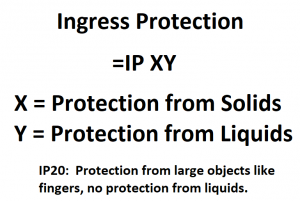
IP Rating for solid objects.
The numbers indicate conformity with the conditions shown below with the first digit indicating the level of protection that the enclosure provides against access to hazardous parts (e.g., electrical conductors, moving parts) and the ingress of solid foreign objects.
Solid foreign objects can be anything from fingers (ouch!) to tools to dust and anything in between. Knowing what degree of protection the housing provides should be a key part of health and safety planning both for existing equipment and new purchases.
For further information on IP Rating is available using the following links:
- IEC 60529 – “Degrees of protection provided by enclosures (IP Code)”
- IEC Standards
- NEMA Enclosure Ratings
- Wikipedia Article – “IP Code“
MOTOR MOUNTING CODES
MOTOR MOUNTING CODES
There are two different standards—NEMA and IEC— which you will see when looking at electric motor mounting positions. Although they are generally comparable, there are slight differences between the two.
Motor Mounting Arrangements (IEC standard 60034-7)

Proper motor installation and mounting position is essential in obtaining top-quality operation, efficient performance, and maximum reliability. Sometimes, however, there is confusion about the many different ways a motor can be installed.
There are two different standards—NEMA and IEC— which you will see when looking at electric motor mounting positions. Although they are generally comparable, there are slight differences between the two.
The standard IEC mounting position places the junction box on the top of the motor, known as the IM B3 mounting position in IEC frame (or F3 in NEMA frames). On the other hand, the NEMA standard mounting position is referred to as F1, with the junction/conduit box located on the left side of the motor facing the output shaft.
The design of most motors is such that they can usually be operated in many mounting positions, unless indicated otherwise. Some mounting positions, however, require additional construction modifications to achieve optimal performance. For example, shaft-up or shaft-down outdoor applications may require drilling of additional drain holes, drip covers and stronger bearings to support heavy loads. Don't just assume you can bolt any motor in any orientation!
Below is a visual reference of typical electric motor mounting positions. Whether you're an installer, engineer, or maintainer, this is a must -have reference.
Subscribe to:
Posts (Atom)