Saturday, June 12, 2021

Interview Questions

1 . IP 69

2. CLASS H

3. How Criticality Calculation is done- ENVIRONMENT, SAFETY, PRODUCTION COST

4. DISCIPLINE FOR ATHLETES

5. ESP HV VOLTAGE

6. GAS EMISSION LIMIT OF ESP

7. CONTAINS OF SMOKE

8. BUDGETING HOW IS DONE - MAINTENANCE 3 STEPS?

9. KRA for Projects

10. KRA for Maintenance


Equipment critical analysis: The need for an effective maintenance program

Oil refineries and large petrochemical plants contain thousands of pieces of process and utilities equipment that are subject to wear, erosion, deterioration, aging, etc., resulting in increasing breakdowns and outages. Imagine being a maintenance engineer and receiving 50 work orders during an overhaul with a limited budget, time, labor, spare parts, tools, machines, etc. How does that engineer prioritize the work?

Zardynezhad, S., Toyo Engineering Canada Ltd.

Oil refineries and large petrochemical plants contain thousands of pieces of process and utilities equipment that are subject to wear, erosion, deterioration, aging, etc., resulting in increasing breakdowns and outages. Imagine being a maintenance engineer and receiving 50 work orders during an overhaul with a limited budget, time, labor, spare parts, tools, machines, etc. How does that engineer prioritize the work?

An important daily challenge at all hydrocarbon processing plants is equipment failure, which can have many causes and consequences. End users not only investigate causes, but also determine the best strategy to mitigate or avoid consequences. The consequences of an equipment failure include risks related to:

  • Safety
  • Environment
  • Production loss
  • Maintenance cost.

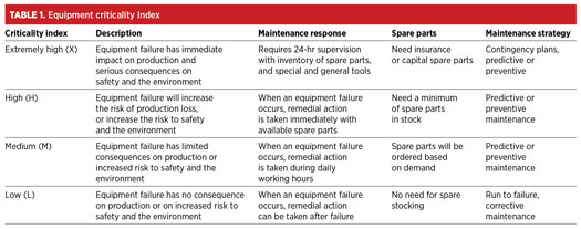
Each type of equipment has a unique role with a different criticality index. Criticality is the failure’s consequence in relation to health, safety, environment, loss of production and maintenance cost (TABLE 1). Selecting the equipment criticality index is explained in the following sections.

EQUIPMENT CRITICAL ANALYSIS

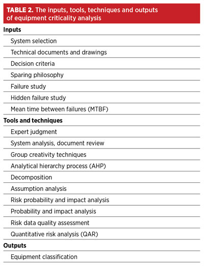
Equipment critical analysis is a quantitative analysis of equipment faults, and ranking them in order of serious consequences on safety, environment, production loss and maintenance cost. The key benefit of this analysis is to provide the means to recognize high-criticality vs. low-criticality equipment, reduce the level of uncertainty and focus on high-priority maintenance tasks. The analysis also helps select the best and most economic maintenance strategy, prioritize work orders and decide on insurance and the demand on spare parts. The inputs, tools, techniques and outputs of this analysis are depicted in TABLE 2.

Input

The first step is to clarify the main systems inside a plant with unit boundaries. This action is normally accomplished by marking up piping and instrumentation diagrams (P&IDs) into main and sub-systems. For example, a gas compression unit in a gas plant can be divided as:

  • Main system—scrubbing, compression, cooling and other auxiliary systems
  • Sub-systems—includes components of the main system. For example, scrubbing would include scrubbers, pressure safety valves (PSVs), shutdowns, alarms, etc. as sub-systems.

For criticality analysis, the following drawings and documentation should be available: detailed plant/system description or control narratives, datasheets, P&IDs, process flow diagrams (PFDs), single-line diagrams, cause-and-effect diagrams, shutdown logic, etc.

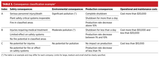
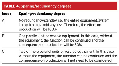
To conduct the analysis, which mainly assesses the consequences of equipment failures and the degree of sparing and redundancy, the consequence classes must be properly defined prior to beginning the analysis. This helps assess the consequences of equipment failures, and the degree of sparing and redundancy. The definition of the consequence classes should be conducted in accordance with the company’s criteria for safety and the environment, and reflect actual plant operations for determining economic losses, such as costs related to lost operation. Decision criteria normally includes four main indexes for safety, environment, production, and operation and maintenance costs. Typically, each index contains a table with three different levels (A, B, C), as shown in TABLES 3 and 4.

Hidden faults that are not evident to the operator during normal operation should also be considered as input to the assessment.

Tools and techniques

Expert judgment should apply to the inputs used to develop the equipment criticality list/classification, and to all technical details during this assessment. Such expertise is provided by any group or individual with specialized knowledge or training in safety, cost estimation, operation, maintenance, environment, health, design, etc. Document analysis is used as another tool. A wide range of documents and drawings may be analyzed to help provide a more effective and efficient study.

Several group creativity activities, such as brainstorming, nominal group techniques, etc., can be organized to assess equipment. The analytical hierarchy process (AHP) method can be used as a powerful tool to prioritize assets according to their criticality. The AHP is built on three basic principles: decompositions, comparative judgment and hierarchy composition of synthesis priorities. Decomposition is another technique for dividing and subdividing systems and sub-systems into smaller components. A criticality assessment and respective plan are developed based on a set of hypotheses and assumptions.

  • An assumptions analysis validates all assumptions used during the study, and identifies risks to the assessments due to inaccuracy or incompleteness of the assumptions.
  • A risk probability analysis covers the probability that specific failure risk will occur. Risk impact analysis includes potential consequences and effects on safety, health, environment, production, and operational and maintenance costs.
  • Risk data quality assessment is a technique to evaluate the degree to which the data about risks is useful for risk management (i.e., the degree to which the risk is understood and the accuracy, quality, reliability and integrity of the data about the risk). Using quantitative risk analysis (QRA), the effect of identified failure risks on operational and maintenance costs, safety, health and environments can be quantitatively analyzed.

Application of equipment criticality index

The result of the assessment will be an equipment criticality list or classification. Advantages of the criticality list are that it:

  • Determines the most efficient, effective and economic maintenance strategy for each piece of equipment (e.g., predictive maintenance, preventive maintenance, run to failure, corrective maintenance, total productive maintenance, etc.)
  • Is a valuable input report to determine the optimum and economic spare parts inventory needed, and to decide which piece of equipment needs insurance or capital spare parts
  • Helps determine the overall priority for performing maintenance tasks when many maintenance activities, or “work order priorities” exist
  • Determines, at a high level, the risk mitigation strategy to be applied to equipment (i.e., condition monitoring and defect elimination on high-criticality items)
  • Helps operators decide conceptual and design evaluations of the high-critical equipment, and prepare the corrective actions
  • Helps reliability engineers focus on reliability improvement efforts on the most “critical” equipment.

Mean time between failures (MTBF)

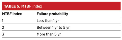
To analyze and determine the equipment criticality index, personnel must define a maintenance index, an index of probability of failure or an MTBF index (TABLE 5).

Using evaluation tables for assessment

First, to define and classify failure for the equipment, the following questions should be addressed:

  • What are the consequences if the equipment works below the requirements?
  • What are the consequences if the equipment is completely out of service?

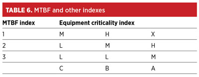
Next, consider the most serious and actual equipment failure scenario. Performance degradation due to equipment failure should also be considered. The effect of failure on safety, environment, production, and operational and maintenance costs is determined and integrated into the MTBF index (TABLE 6).

CASE STUDY

Typically, naphtha hydrotreaters and octanizer units in oil refineries contain 13 hydrogen (H2) gas compressors to boost, recycle or export H2 gas. In this case study, the main 5-MW, API 618 standard H2 recycle gas compressors were considered. Each reciprocating compressor had a 100% spare machine with two stages and four throws.

Possible compressor failures include:

  • Valve failure
  • Coupling failure
  • Piston rings failure
  • Cross head shoes failure
  • Bearing failures.

Coupling bearing and cross failures are the most serious failures, and can result in the compressor being put out of service.

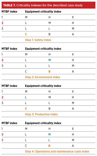
Step 1: Safety index evaluation. TABLE 3 results to Index C, because there is no potential for injury and/or fire after failure.

Step 2: Environment index evaluation. TABLE 3 results to Index B, because compressor cylinders’ gas should be sent to the flare to allow workers to begin maintenance activity on the failed compressor.

Step 3: Production index evaluation. TABLES 3 and 4 result to Index C, because there is a spare machine, which causes no impact on production.

Step 4: Operation and maintenance cost index. TABLE 3 results to Index B. The cost of spare parts, gas sent to the flare, manpower cost, tools, etc. are assumed to be less than $30,000.

Note: MTBF index. TABLE 5 results to Index 2, with reference to maintenance experience, type of bearing and vendor’s recommendation, it was learned that the bearing failure was more than 5 yr old.

Based on TABLES 3, 4, 5 and 6, the criticality indexes for this case study are shown in Table 7. 


Wednesday, April 21, 2021

ARC FLASH SUIT

 Air Compressor 

type- positive displacement (reciprocating-high capacity), rotary type(screw, centrifugal) ---

capacity - cfm 

Arc Flash Suit Functionality

To be functional, an arc flash suit must:

  • Be wearable by men and women
  • Be available in several sizes and fit a wide range of people
  • Be ergonomically shaped (comfortable to wear)
  • Include only arc-rated items
  • Include garments such as boots, helmet, gloves that provide full-body protection

Manufacturers of arc flash suits must rely on designers, material scientists, and other professionals (tailors, leatherworkers, etc.) to create functional garments. Arc flash suits must also be tested and proven to fit within the NFPA PPE Arc categories or they will not be deemed safe.

What Are the Features of Arc Flash Suits?

Arc flash suits consist of a one-piece suit with protective gloves and special socks. 

The outer layer is made of metalized polyamide fabric, 

The inner layer is of hydrophilic cotton fabric that adheres to the body.

Arc Flash Suit Ratings Guide


Arc flash suits consist of a one-piece suit with protective gloves and special socks. The outer layer is made of metalized polyamide fabric, and the inner layer is of hydrophilic cotton fabric that adheres to the body.

It has a suit hood to protect the head. Below the hood, there is a plastic helmet with a wrap. The voltages at workplaces requiring arc suits are extremely large, over 400 kV (at plants up to 800kV), so a visor for face protection and a helmet is needed. Socks have a three-layer structure, and their lower parts are connected by metal buckles to the suit’s legs.

The seams at the suits must be made so that the metalized layers of the fabric come on top of each other to achieve electrical conductivity. Namely, there is a whole mathematical model for calculating the protection of current flow and is taught in vocational textile schools.


Arc Flash Suit Ratings Guide

The arc flash suit ratings are based on the resistance of the suit’s material to energies released during an arc flash. This means how much energy the material can deflect or absorb before it gets damaged or allows for the burning of the skin. 

The arc flash rating is defined as how much heat energy the arc suit can withstand per square centimeter (cal/cm2.) 

Arc flash suits with higher resistance have higher ratings and vice versa. 

Arc Flash PPE Categories 

The National Fire Protection Association (NFPA) has defined 4 categories for arc flash suits in its NFPA 70E (2018) guidelines. These are determined by arc incident energy analysis measured as calories per centimeter squared (cal/cm2.) They include the following categories:

  • PPE Category 1: Minimum Arc Rating of 4 cal/cm2
  • PPE Category 2: Minimum Arc Rating of 8 cal/cm2
  • PPE Category 3: Minimum Arc Rating of 25 cal/cm2
  • PPE Category 4: Minimum Arc Rating of 40 cal/cm2


Arc Flash Category 1 Clothing / PPE

The following are arc-rated garments or gear required to fit PPE category 1:

  • Arc rated long sleeve shirt, jacket, pants, coverall with a minimum arc rating of 4 cal/cm2.
  • Face shield with wrap guarding, balaklava, or arc flash suit hood.

Additional garments include:

  • Arc rated jacket, parka, hard hat liner, or rain gear.

Arc Flash Category 2 Clothing / PPE

The following arc-rated garments or gear are required to fit PPE category 2:

  • Arc rated long sleeve shirt, pants, coverall with a minimum of 8 cal/cm2
  • Arc rated flash suit hood or face shield, sock hood (balaclava) with a minimum arc rating of 8 cal/cm2

Additional garments include:

  • Arc rated jacket, parka, hard hat liner, or rain gear.
  • Heavy-duty leather gloves
  • Hard hat, glasses, goggles, hearing protection
  • Leather boots or footwear

Arc Flas Category 3 Clothing / PPE

The following are arc-rated garments or gear required to fit PPE category 3:

  • Arc rated suit jacket, pants, coveralls with a minimum arc rating of 25 cal/cm2.
  • Arc rated flash suit hood with a minimum arc rating of 25 cal/cm2
  • Rubber insulating gloves with leather protectors, or arc-rated gloves

Additional garments include:

  • Arc rated jacket, parka, rain gear, and hard hat liner

Arc Flash Category 4 Clothing / PPE

The following arc-rated garments or gear are required to fit PPE category 4:

  • Arc rated flash suit jacket and pants, or coveralls with a minimum arc rating of 40 cal/cm2.
  • Arc rated flash suit hood with a minimum arc rating of 40 cal/cm2
  • Rubber insulating gloves with leather protectors, or arc-rated gloves

Additional garments include:

  • Arc rated jacket, parka, hard hat liner, or rain gear

Arc Flash Suit Ratings are Critical

Arc flash suits are specially designed safety garments that meet critical PPE standards set by the National Fire Protection Association. Be sure to only use an arc flash suit that meets these ratings when working with electrical equipment or in high arc-risk environments.

Wednesday, February 3, 2021

Differences Between Earthed and Unearthed Cables-EE AND UE


Introduction

In HT electrical distribution, the system can be earthed or unearthed. The selection of unearthed or earthed cable depends on distribution system. If such system is earthed, then we have to use cable which is manufactured for earthed system. (which the specifies the manufacturer). If the system is unearthed then we need to use cable which is manufactured for unearthed system.


The unearthed system requires high insulation level compared to earthed system.

For earthed and unearthed XLPE cables, the IS 7098 part2 1985 does not give any difference in specification. The insulation level for cable for unearthed system has to be more.


Earthed System

Earlier the generators and transformers were of small capacities and hence the fault current was less. The star point was solidly grounded. This is called earthed system.

In three phases earthed system, phase to earth voltage is 1.732 times less than phase to phase voltage. Therefore voltage stress on cable to armor is 1.732 times less than voltage stress between conductors to conductor.

Where in unearthed system, (if system neutral is not grounded) phase to ground voltage can be equal to phase to phase voltage. In such case the insulation level of conductor to armor should be equal to insulation level of conductor to conductor.

In an earthed cable, the three phase of cable are earthed to a ground. Each of the phases of system is grounded to earth.

Example: 1.9/3.3 KV, 3.8/6.6 KV system

Unearthed System

Today generators of 500MVA capacities are used and therefore the fault level has increased. In case of an earth fault, heavy current flows into the fault and this lead to damage of generators and transformers. To reduce the fault current, the star point is connected to earth through a resistance. If an earth fault occurs on one phase, the voltage of the faulty phase with respect to earth appears across the resistance.

Therefore, the voltage of the other two healthy phases with respect to earth rises by 1.7 times.

If the insulation of these phases is not designed for these increased voltages, they may develop earth fault. This is called unearthed system.

In an unearth system, the phases are not grounded to earth .As a result of which there are chances of getting shock by personnel who are operating it.

Example: 6.6/6.6 KV, 3.3/3.3 KV system.

Unearthed cable has more insulation strength as compared to earthed cable. When fault occur phase to ground voltage is √3 time the normal phase to ground voltage. So if we used earthed cable in unearthed System, It may be chances of insulation puncture.

So unearthed cable are used. Such type of cable is used in 6.6 KV systems where resistance type earthing is used.

Nomenclature

In simple logic the 11 KV earthed cable is suitable for use in 6.6 KV unearthed system. The process of manufacture of cable is same.

The size of cable will depend on current rating and voltage level.

  • Voltage Grade (Uo/U) where Uo is Phase to Earth Voltage & U is Phase to Phase Voltage.
  • Earthed system has insulation grade of KV / 1.75 x KV.
  • For Earthed System (Uo/U): 1.9/3.3 kV, 3.8/6.6 kV, 6.35/11 kV, 12.7/22 kV and 19/33 kV.
  • Unearthed system has insulation grade of KV / KV.
  • For Unearthed System (Uo/U): 3.3/3.3 kV and 11/11 kV.
  • 3 phase 3 wire system has normally Unearthed grade cables and 3 phase 4 wire systems can be used earthed grade cables, insulation used is less, and cost is less.

Thumb Rule

As a thumb rule we can say that 6.6KV unearthed cable is equal to 11k earthed cable i.e 6.6/6.6kv Unearthed cable can be used for 6.6/11kv earthed system.

Because each core of cable have the insulation level to withstand 6.6kv so between core to core insulation level will be 6.6kV+6.6kV = 11kV

For transmission of HT, earthed cable will be more economical due to low cost where as unearthed cables are not economical but insulation will be good.

Generally 6.6 kV and 11kV systems are earthed through a neutral grounding resistor and the shield and armor are also earthed, especially in industrial power distribution applications.  Such a case is similar to an unearthed application but with earthed shield (sometimes called solid bonding).

In such cases, unearthed cables may be used so that the core insulation will have enough strength but current rating is de-rated to the value of earthed cables.

But it is always better to mention the type of system earthing in the cable specification when ordering the cables so that the cable manufacturer will take care of insulation strength and de rating.

Thursday, January 28, 2021

Core Balance Current Transformer - CBCT


Core Balance Current Transformer-CBCT:

Core-Balance Current Transformer CBCT also called as Zero Sequence CT.

In this type of CT a single ring or rectangular shaped core of magnetic material, encircles the conductors of all the three phases. A secondary coil is wound on the core connected to a relay circuit.

Core Balance Current Transformer without Cable Termination
CBCT inside Cable chamber without Cable

This ground fault relay, detects the ground leakage current and trips the faulty circuit.

The topics covered in this post are

Principle of CBCT

  • Mounting of CBCT
  • Selection of CBCT
  • CBCT for Motor protection

Principle of CBCT for Earth fault Protection:

In absence of an earth fault in the load or the supply cable, the current in the secondary of Core Balance Current Transformer is negligible. Under balanced load and without earth fault,

Ie= (Ir+ Iy+ Ib) =0

However during an earth fault on load side of zero sequence CT,

Ie= (Ir+ Iy+ Ib) =3 I0

Where I0 is the zero sequence component.

The relay connected on secondary side of CBCT (Zero Sequence CT) senses this current and thus it will operate.

Core-Balance Current Transformer Mounting:

The following is the correct procedure for the proper mounting of these CTs.

1.It is necessary to pass all the Three, Three and half or Four cores of the cable through the core of the CBCT to detect the unbalance or the ground leakage in 3-core cables and only ground leakage in 3-1/2 and 4 core cables.

Core Balance Current Transformer with 3-Core Cable Termination
CBCT with 3-Core Cable
  • Three Core cable:  A 3-core cable will detect an unbalance in the three phases, whether this is the result of unequal loading in the three phases or a ground fault.
  • Three and half or Four Core Cables: These cables will detect only a ground leakage as the amount of unbalance, when unbalance occurs, will be offset by the flow of this unbalance current through the return path of neutral circuit.

2. In armoured cables, armouring must be removed before passing the cable through the CBCT to avoid an induced e.m.f through the armour and the corresponding magnetizing current which may affect the performance of the current transformer.

3. As such CTs are required to detect small out-of-balance currents, the connecting leads should be properly terminated and must be short to contain the lead resistance as far as possible.

Selection of CBCT:

The required CBCT is selected based on the following factors.

  • Minimum primary ground leakage current
  • Nominal CT ratio. This may be such that on the smallest ground fault the current on the secondary is sufficient to operate the relay.
  • Relay setting
  • CT secondary current, 1A or 5A
  • Minimum excitation current required at the relay operating voltage
  • Knee point voltage
  • Number of cables in parallel
  • Limiting dimensions and internal diameter (ID) of the CT. ID will depend upon the size of the cable.

CBCT for Motor Protection:

CBCT is used in motor protection for providing Zero sequence protection. The core of core- balance CT surrounds the power cable connected to the induction motor. The earthing lead from the cable-sheath to earth must be taken through the eye of the CT core.

Core Balance Current Transformer Protection for 3-Phase Motor
Motor Protection with CBCT

The CT core is excited by ir+ iy+ ib+ isheath+ iearth. The effect of (isheath+ iearth) is cancelled when the earth lead is taken through the eye of CT core. There by the protection responds only to ir+ iy+ ib value current.