1. ABOUT YOURSELF
experience
work profile
company
family
tanδ is a measure of the imperfection of the dielectric nature of insulation materials like oil.
2. CONSTRUCTION POWER RATE - 18 Rs
3. CONSTRUCTION BILL COMPONENTS
4. TRANSFORMER TEST
Type of Transformer Testing
Tests done at Factory
- Type tests
- Routine tests
- Special tests
Tests done at Site
- Pre-commissioning tests
- Periodic/condition monitoring tests
- Emergency tests
Special Tests of transformer include
- Dielectric tests.
- Measurement of zero-sequence impedance of three-phase transformers
- Short-circuit test
- Measurement of acoustic noise level
- Measurement of the harmonics of the no-load current.
- Measurement of the power taken by the fans and oil pumps.
- Tests on bought out components / accessories such as buchhloz relay, temperature indicators, pressure relief devices, oil preservation system etc.
Transformer Winding Resistance Measurement
Transformer winding resistance measurement is carried out to calculate the I2R losses and to calculate winding temperature at the end of a temperature rise test. It is carried out as a type test as well as routine test. It is also done at site to ensure healthiness of a transformer that is to check loose connections, broken strands of conductor, high contact resistance in tap changers, high voltage leads and bushings etc.
There are different methods for measuring of the transformer winding, likewise:
- Current-voltage method of measurement of winding resistance.
- Bridge method of measurement of winding resistance.
- Kelvin bridge method of Measuring Winding Resistance.
- Measuring winding resistance by Automatic Winding Resistance Measurement Kit.
Note: Transformer winding resistance measurement shall be carried out at each tap.
Transformer Ratio Test
The performance of a transformer largely depends upon perfection of specific turns or voltage ratio of transformer. So transformer ratio test is an essential type test of transformer. This test also performed as a routine test of transformer. So for ensuring proper performance of electrical power transformer, voltage and turn ratio test of transformer one of the important tests.
The procedure of the transformer ratio test is simple. We just apply three phase 415 V supply to HV winding, with keeping LV winding open. We measure the induced voltages at HV and LV terminals of the transformer to find out actual voltage ratio of the transformer. We repeat the test for all tap position separately.
Magnetic Balance Test of Transformer
Magnetic balance test of transformer is conducted only on three-phase transformers to check the imbalance in the magnetic circuit.
Procedure of Magnetic Balance Test of Transformer
- Keep the tap changer of transformer in normal position.
- Now disconnect the transformer neutral from ground.
- Then apply single phase 230 V AC supply across one of the HV winding terminals and neutral terminal.
- Measure the voltage in two other HV terminals in respect of neutral terminal.
- Repeat the test for each of the three phases.
In case of an autotransformer, a magnetic balance test of transformer should be repeated for LV winding also.
There are three limbs placed side by side in a core of the transformer. One phase winding is wound in one limb. The voltage induced in different phases depends upon the respective position of the limb in the core. The voltage induced in different phases of a transformer in respect to neutral terminals given in the table below.
Magnetizing Current Test of Transformer
Magnetizing current test of transformer is performed to locate defects in the magnetic core structure, shifting of windings, failure in between turn insulation or problem in tap changers. These conditions change the effective reluctance of the magnetic circuit, thus affecting the current required to establish flux in the core.
- Keep the tap changer in the lowest position and open all IV and LV terminals
- Then apply three phase 415 V supply on the line terminals for three-phase transformers and single phase 230 V supply on single phase transformers
- Measure the supply voltage and current in each phase
- Now repeat the magnetizing current test of transformer test with keeping tap changer in normal position
- Repeat the test while keeping the tap at highest position
Normally, there are two similar higher readings on two outer limb phases on transformer core and one lower reading on the center limb phase, in the case of three phase transformers.
An agreement to within 30% of the measured exciting current with the previous test is usually considered satisfactory. If the measured exciting current value is 50 times higher than the value measured during factory test, there is a likelihood of a fault in the winding which needs further analysis.
Caution: This magnetizing current test of a transformer is to be carried out before DC resistance measurement.
Vector Group Test of Transformer
In a 3 phase transformer, it is essential to carry out a vector group test of transformer. Proper vector grouping in a transformer is an essential criteria for parallel operation of transformers.
There are several internal connections of three-phase transformer are available on the market. These several connections give various magnitudes and phase of the secondary voltage; the magnitude can be adjusted for parallel operation by suitable choice of turn ratio, but the phase divergence cannot be compensated.
So we have to choose a transformer suitable for parallel operation whose phase sequence and phase divergence are same. All the transformers with the same vector ground have same phase sequence and phase divergence between primary and secondary.
Before procuring an electrical power transformer, you should ensure the vector group of the transformer, whether it will be matched with his or her existing system or not. The vector group test of transformer confirms his or her requirements.
Insulation Resistance Test or Megger Test of Transformer
Insulation resistance test of transformer is essential type test. This test is carried out to ensure the healthiness of the overall insulation system of an electrical power transformer.
Procedure of Insulation Resistance Test of Transformer
- Disconnect all the line and neutral terminals of the transformer
- Megger leads to be connected to LV and HV bushing studs to measure insulation resistance IR value in between the LV and HV windings
- Megger leads to be connected to HV bushing studs and transformer tank earth point to measure insulation resistance IR value in between the HV windings and earth
- Megger leads to be connected to LV bushing studs and transformer tank earth point to measure insulation resistance IR value in between the LV windings and earth
NB: It is unnecessary to perform insulation resistance test of transformer per phase wise in three-phase transformer. IR values are taken between the windings collectively as because all the windings on HV side are internally connected together to form either star or delta and also all the windings on LV side are internally connected together to form either star or delta.
Measurements are to be taken as follows:
- For autotransformer: HV-IV to LV, HV-IV to E, LV to E.
- For two winding transformer: HV to LV, HV to E, LV to E.
- Three winding transformers: HV to IV, HV to LV, IV to LV, HV to E, IV to E, LV to E.
- Oil temperature should be noted at the time of insulation resistance test of the transformer, since the IR value of transformer insulating oil may vary with temperature.
- IR values to be recorded at intervals of 15 seconds, 1 minute and 10 minutes.
- With the duration of application of voltage, IR value increases. The increase in IR is an indication of dryness of insulation.
- Absorption coefficient = 1 minute value/15 secs. value.
- Polarization index = 10 minutes value/1 minute value.
Dielectric Tests of Transformer
Dielectric test of a transformer is one kind of insulation test. This test is performed to ensure the expected overall insulation strength of the transformer. There are several tests performed to ensure the required quality of transformer insulation; the dielectric test is one of them. Dielectric test of the transformer is performed in two different steps.
First one is called Separate Source Voltage Withstand Test of transformer, where a single phase power frequency voltage of prescribed level, is applied on transformer winding under test for 60 seconds while the other windings and tank are connected to the earth, and it is observed that whether any failure of insulation occurs or not during the test.
The second one is the induced voltage test of Transformer where, three-phase voltage, twice of rated secondary voltage is applied to the secondary winding for 60 seconds by keeping the primary of the transformer open circuited.
The frequency of the applied voltage should be double of power frequency too. Here also if no failure of insulation, the test is successful.
In addition to dielectric tests of transformers, there are other types of test for checking insulation of transformer, such as lightning impulse test, switching impulse test and partial discharge test.
Induced Voltage Test of Transformer
The induced voltage test of the transformer is intended to check the inter-turn and line end insulation as well as main insulation to earth and between windings-
- Keep the primary winding of transformer open circuited.
- Apply three-phase voltage to the secondary winding. The applied voltage should be twice of the rated voltage of secondary winding in magnitude and frequency.
- The duration of the test shall be 60 seconds.
- The test shall start with a voltage lower than 1/3 the full test voltage, and it shall be quickly increased up to the desired value.
The test is successful if no breakdown occurs at full test voltage during the test.
Temperature Rise Test of Transformer
Temperature rise test of transformer is included in type test of transformer. In this test, we check whether the temperature-rising limit of the transformer winding and oil as per specification or not. In this type test of the transformer, we have to check oil temperature rise as well as winding temperature rise limits of an electrical transformer.
5. TRANSFORMER OIL NAME
It is generally obtained from fractional distillation and subsequent treatment of crude petroleum.
That is why this oil is also known as Mineral Insulating Oil.
Chemical formula: DIFLORO DICHLORO ETHYL BENZENE .
Transformer oil: Testing, Types, and Properties
Transformer oil types have properties that contribute to the safe and smooth operation of the transformers.
Table of Contents
1. What is the transformer oil?
2. Types of Transformer Oil
a. Naphthenic Oil
b. Paraffinic Oil
3. Ideal Properties of Transformer Oil
a. Electrical Properties of Transformer Oil
b. Chemical Properties of Transformer Oil
c. Physical Properties of Transformer Oil
4. Transformer Oil Testing
5. Why is Transformer Oil Testing Important?
1. What is the transformer oil?
Transformer oil (also known as insulating oil) is a special type of oil that has excellent electrical insulation and is stable at high temperatures.
Oil-immersed transformers use oil for the purpose of
1. insulation,
2. stopping the discharge and aura discharge,
3. at the same time dissipating the heat of the transformer (i.e. acting as a coolant).
4. Preserve the transformer’s core and windings by fully immersed them inside the oil.
5. Another important property of the insulating oil is the prevention of oxidation of the cellulose-made paper insulation. The transformer oil likes as a barrier between the atmospheric oxygen and the cellulose – avoiding direct contact and hence minimizing oxidation.
The level of transformer oil is measured using a MOG (Magnetic Oil level Gauge).
2. Types of Transformer oil
There are two main types of transformer oil used today:
Paraffin-based transformer oil and Naphtha-based transformer oil.
a. Naphthenic Oil
The mineral insulating oil is derived from particular crudes, which include extremely low n-paraffin known as wax.
This oil's pour point is low compared with the paraffinic type due to less wax content.
The boiling point of this oil is approximately 425 °C.
As compared with other oil, this is more readily corroded.
The products of oxidation are soluble within the oil.
The corrosion of paraffin-based crudes generates an unsolvable sludge to increase the viscosity. So it will reduce the capacity of heat transfer, service life, and overheating.
These oils include aromatic compounds at relatively fewer temperatures, like -40°C.
b. Paraffinic Oil
Mineral insulating oil derived from special crudes contains a substantial amount of n-paraffin, i.e., wax.
This oil's pour point is high compared with the naphthenic type due to high wax content.
The boiling point of this kind of oil about 530 °C.
Oxidation of this oil is less.
Oxidation products are insoluble within the oil.
Even though the naphthenic type is more readily corroded than paraffinic, the oxidation products are soluble within the oil that results in a decrease of problem.
In theory, Paraffin-based oil is not as easily oxidized as naphtha-based oil is, producing less sludge. Cause sludge naphtha-based oil is more soluble than paraffin-based oil, so whatever sludge naphtha-based oil generates is more easily removed than the sludge from paraffin-based oil. If sludge builds up at the bottom of a transformer container, it'll interfere with the transformer operation.
The Naphtha-based oil and paraffin-based oil do not contain dissolved wax. This wax can increase the pour point and potentially cause issues, but in warmer climates where the temperature never gets very low, this is not an issue.
However, paraffin oil is the most commonly used type of oil in transformers worldwide, despite naphtha-based oil has more apparent superiority.
3. Ideal Properties of Transformer Oil
- Electrical properties: Specific resistance, dielectric strength, dielectric dissipation factor.
- Chemical properties: Water content, acidity, sludge content.
- Physical properties: Interfacial tension, viscosity, flash point, pour point.
a. Electrical Properties of Transformer Oil
- Dielectric Dissipation Factor of Tan Delta of Transformer Oil
b. Chemical Properties of Transformer Oil
c. Physical Properties of Transformer Oil
- Pour Point of Transformer Oil
- Viscosity of Transformer Oil
a. Electrical Properties of Transformer Oil
The dielectric strength of transformer oil is also known as the transformer oil's breakdown voltage (BDV). Breakdown voltage is measured by observing at what voltage, sparking strands between two electrodes immersed in the oil, separated by a specific gap. A low value of BDV indicates the presence of moisture content and conducting substances in the oil.
For measuring BDV of transformer oil, a portable BDV measuring kit is generally available at the site. In this kit, oil is kept in a pot in which one pair of electrodes are fixed with a gap of 2.5 mm (in some kit, it 4mm) between them. Now slowly rising voltage is applied between the electrodes. The rate of increasing voltage is controlled at 2 KV/s and observe the voltage at which sparking starts between the electrodes - that means at which voltage dielectric strength of transformer oil between the electrodes has been broken down.
This measurement is taken 3 to 6 times in the same oil sample, and we take the average value of these readings. BDV is the primary indicator of the health of oil. So it’s a popular and important test of transformer oil and it can be easily carried out at the site.
Dry and clean oil gives BDV results, better than the oil with moisture content and other conducting impurities. The minimum breakdown voltage of transformer oil or dielectric strength of transformer oil at which this oil can safely be used in the transformer is considered 30 KV.
- Specific Resistance of Transformer Oil
This is another important property of transformer oil. The specific oil resistance is a measure of DC resistance between two opposite sides of one cm3 block of oil. Its unit is ohm-cm at a particular temperature. With an increase in temperature, the resistivity of oil decreases rapidly.
Just after charging a transformer after long shut down, the oil temperature will be at ambient temperature, and during full load, the temperature will be very high. It may go up to 90ºC at an overload condition. The insulating oil's resistivity must be high at room temperature, and it should have good value at high temperatures.
That is why specific resistance or resistivity of transformer oil should get measured at 27ºC and 90ºC.
The minimum standard specific resistance of transformer oil at 90ºC is 35 × 1012 ohm-cm, and at 27ºC, it is 1500 × 1012 ohm-cm.
- Dielectric Dissipation Factor of Tan Delta of Transformer Oil
The dielectric dissipation factor is also known as the loss factor or tan delta of transformer oil. When an insulating material is placed between the live part and the grounded part of electrical equipment, leakage current will flow. As an insulating material is dielectric, the current through the insulation ideally leads the voltage by 90º. Here voltage means the instantaneous voltage between the live part and ground of the equipment. But in reality, no insulating materials are perfect dielectric in nature.
Hence current through the insulator will lead the voltage with an angle a little bit shorter than 90º. The tangent of the angle by which it is short of 90º is called the dielectric dissipation factor or simply tan delta of transformer oil. More plainly, the leakage current through insulation does have two-component one resistive or active, and another one is capacitive or reactive. Again it is clear from the above diagram, the value of ′δ′ is also known as loss angle.
If the loss angle is small, then the resistive component of the current IR is small, which indicates a high resistive property of the insulating material. High resistive insulation is a good insulator. Hence it is desirable to have a loss angle as small as possible. So we should try to keep the value of tanδ as small as possible. The high value of this tanδ is an indication of the presence of contaminants in transformer oil.
Hence there is a clear relationship between tanδ and resistivity of insulating oil. If the value of tan-delta increases, the resistivity of the insulating oil gets decreased and vice versa. So both the resistivity test and tan delta test of transformer oil are generally not required for the same piece of the insulator or insulating oil.
In one sentence, it can be said that tanδ is a measure of the imperfection of the dielectric nature of insulation materials like oil.
b. Chemical Properties of Transformer Oil
Moisture or water content in transformer oil is highly undesirable as it affects the oil's dielectric properties adversely. The water content in oil also affects the paper insulation of the winding and core of a transformer. Paper is highly hygroscopic. Paper absorbs the maximum amount of water from oil, affecting paper insulation property and reducing its life. But in a loaded transformer, oil becomes hotter; hence the solubility of water in oil increases.
As a result, the paper releases water and increases the water content in transformer oil. Thus the temperature of the oil at the time of taking a sample for the test is critical. During oxidation, acids get formed in the oil; the acids give rise to the solubility of water in the oil. Acid, coupled with further, water decompose the oil, forming more acid and water. This rate of degradation of oil increases. We measure the water content in oil as ppm (parts per million units).
The water content in an oil is allowed up to 50 ppm recommended by IS–335(1993). The accurate measurement of water content at such low levels requires a sophisticated instrument like Coulometric Karl Fischer Titrator.
- Acidity of Transformer Oil
Acidic transformer oil is a harmful property. If oil becomes acidic, the water content in the oil becomes more soluble in the oil. The acidity of oil deteriorates the insulation property of paper insulation of winding. Acidity accelerates the oxidation process in the oil. Acid also includes the rusting of iron in the presence of moisture.
The acidity test of transformer oil can be used to measure the acidic constituents of contaminants. We express the acidity of oil in mg of KOH required to neutralize the acid present in a gram of oil. This is also known as a neutralization number.
c. Physical Properties of Transformer Oil
The interfacial tension between the water and oil interface is the way to measure the attractive molecular force between water and oil. in Dyne/cm or milli-Newton/meter. Interfacial tension is exactly useful for determining the presence of oil decay products and polar contaminants. Good new oil generally exhibits high interfacial tension. Oil oxidation contaminants lower the IFT.
- Flashpoint of Transformer Oil
The Flashpoint of transformer oil is the temperature at which oil gives enough vapors to produce a flammable mixture with air. This mixture provides momentary flash on the application of flame under standard condition. Flashpoint is important because it specifies the chances of fire hazard in the transformer. So it is desirable to have a very high flash point of transformer oil. In general, it is more than 140º(>10º).
- Pour Point of Transformer Oil
It is the minimum temperature at which oil starts to flow under the standard test condition. The pour point of transformer oil is a valuable property mainly at the places where the climate is icy. If the oil temperature falls below the pour point, the transformer oil stops convection flowing and obstruct cooling in a transformer. Paraffin-based oil has a higher value of pour point than Naphtha-based oil, but in India, it does not affect the use of Paraffin oil due to its warm climate condition. The pour point of transformer oil mainly depends upon wax content in the oil. As Paraffin-based oil has more wax content, it has a higher pour point.
- Viscosity of Transformer Oil
In a few words, the viscosity of transformer oil can be said that viscosity is the resistance of flow in normal conditions. Resistance to the flow of transformer oil means obstruction of convection circulation of oil inside the transformer. Good oil should have a low viscosity so that it offers less resistance to the conventional flow of oil, thereby not affecting the cooling of a transformer. The low viscosity of transformer oil is essential, but it is equally important that the viscosity of oil should increase as little as possible with a decrease in temperature. Every liquid becomes more viscous if the temperature decreases.
4. Transformer Oil Testing
Transformer oil needs to be tested to ensure that it works for today's standards. Testing standards and procedures are defined by various international standards, and the ASTM sets most of them.
Oil testing consists of measuring the breakdown voltage and other chemical and physical properties of the oil, either through in a laboratory or portable test equipment. The transformer's lifespan is increased through proper testing, reducing the need to pay for the replacement.
Factors to Test:
Here are the most common things to look for when performing a transformer oil test:
- Standard Specification for Mineral Insulating Oil Used in Electrical Apparatus (ASTM D3487)
- Acid number (ASTM D664)
- Dielectric breakdown voltage (ASTM D877)
- Liquid power factor (ASTM D924-08)
- Interfacial tension (ASTM D971)
- Specific resistance (ASTM D1169)
- Corrosive sulfur (ASTM D1275)
- Visual examination (ASTM D1524)
Note: ASTM stands for the American Society for Testing and Materials.
These tests will help determine if the oils are clean and create a baseline of properties that need to be tested periodically. Although there are a large number of available tests, they are expensive. So it's best to use them as diagnostics if an issue occurs during primary testing.
The recommended frequency is dependant on the power and the voltage. If the results from the test are showing some red flags, the frequency will have to increase. Even if the cost of testing is high, the expense should be compared to the cost of replacing a transformer and the downtime associated with losing the transformer.
It's important to understand the difference between excessive and normal gassing rates. The amount of dissolved gas in transformer oil can be found by using a dissolved gas analysis (DGA) test. The gassing rate will vary based on the loading, transformer design, and insulation material.
5. Why is Transformer Oil Testing Important?
Transformer oil testing is important to:
- Determine the essential electrical properties of transformer oil
- Identify if a certain oil is suitable for future use
- Detect whether regeneration or filtration is needed
- Reduce oil costs and enhance component life
- Prevent untimely failures and maximize safety
=> Keep in mind, and transformer oils can last for up to 30 years. So taking the proper testing procedures now will save you thousands of dollars in the long run.
+++++++++++++++++++++++++++++++++++++++++++++++++++++++++++
+++++++++++++++++++++++++++++++++++++++++++++++++++++++++++
6. TRANSFORMER VECTOR GROUP
30 SECONDARY
Procedure of Vector Group Test of Transformer
 connected step down transformer")
Let’s have a YNd11 transformer.
- Connect neutral point of star connected winding with earth.
- Join 1U of HV and 2W of LV together.
- Apply 415 V, three phase supply to HV terminals.
- Measure voltages between terminals 2U-1N, 2V-1N, 2W-1N, that means voltages between each LV terminal and HV neutral.
- Also measure voltages between terminals 2V-1V, 2W-1W and 2V-1W.
For YNd11 transformer, we will find,
2U-1N > 2V-1N > 2W-1N
2V-1W > 2V-1V or 2W-1W .
The vector group test of transformer for other group can also be done in similar way.
Vector Group Test of Transformer
The vector group of transformer is an essential property for successful parallel operation of transformers. Hence every electrical power transformer must undergo through vector group test of transformer at factory site for ensuring the customer specified vector group of transformer.
The phase sequence or the order in which the phases reach their maximum positive voltages, must be identical for two paralleled transformers. Otherwise, during the cycle, each pair of phases will be short circuited.
The several secondary connections are available in respect of various primary three phase connection in a the three phase transformer. So for same primary applied three phase voltage there may be different three phase secondary voltages with various magnitudes and phases for different internal connection of the transformer.
Let’s have a discussion in detail by example for better understanding.
We know that, the primary and secondary coils on any one limb have induced emfs that are in time-phase. Let’s consider two transformers of same number primary turns and the primary windings are connected in star. The secondary number of turns per phase in both transformers are also same. But the first transformer has star connected secondary and other transformer has delta connected secondary. If same voltages are applied in primary of both transformers, the secondary induced emf in each phase will be in same time-phase with that of respective primary phase, as because the the primary and secondary coils of same phase are wound on the same limb in the core of transformer. In first transformer, as the secondary is star connected, the secondary line voltage is √3 times of induced voltage per secondary phase coil. But in case of second transformer, where secondary is delta connected, the line voltage is equal to induced voltage per secondary phase coil. If we go through the vector diagram of secondary line voltages of both transformer, we will easily find that there will be a clear 30o angular difference between the line voltages of these transformers.
Now, if we try to run these transformers in parallel then there will be a circulating current flows between the transformers as because there is a phase angle difference between their secondary line voltages. This phase difference can not be compensated. Thus two sets of connections giving secondary voltages with a phase displacement can not be intended for parallel operation of transformers.
The following table gives the connections for which from the view point of phase sequence and angular divergences, transformer can be operated parallel. According to their vector relation, all three phase transformers are divided into different vector group of transformer. All electrical power transformers of a particular vector group can easily be operated in parallel if they fulfill other condition for parallel operation of transformers.
| GROUP | Connection | Connection |
|---|
0
(0o) | | |
|---|
1
( 30o) | | |
|---|
6
( 180o) | | |
|---|
11
( – 30o) | | |
|---|
7. TRANSFORMER VECTOR GROUP HOW 30DEG IS CREATED
8. FLP MOTORS MEANING
9. TYPES OF ZONE PROTECTION AND ITS TYPES
10. WHAT DO YOU MEAN BY EX-D
An Ex d enclosure is designed to contain an explosion and stop any flames, sparks, and hot gases from escaping into the surrounding atmosphere should an internal explosion occur. In addition, an Ex d enclosure protects the fitted equipment against external moisture, dirt, dust, or water.
11. OTHER TYPE THAN EX-D
12. HT CABLE TESTING
13. FLAMIBILITY DIAMOND SHAPED PLACARD- NFPA 704
NFPA 704 is the labeling system used to identify hazardous materials within a building that is published by the National Fire Protection Association (NFPA).
NFPA 704 is a supplemental labeling system specifically intended for emergency responders, though other people can read and benefit from these labels in normal working conditions.
The NFPA 704 Diamond is a diamond-shaped placard that is divided into four sections.
Each of the four sections is colored differently
Red, Yellow , Blue and White and
is used to indicate different types of hazards (flammability, health, instability, and special notes).
White is indicative of a special hazard.
Each section is typically filled in with a number between 0 and 4, which indicates the level of hazard that exists, 0 being the lowest and 4 being the highest.
14. Motor Insulation Class
B 130
F 155
H 180
Deg Celcius
AE BFH NRSC. - 9
AEeee BF Hai na Rohan ko SeCretary
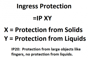
15. IP RATING